TM 5-4240-501-14P
IGNITION
Magna-Matic
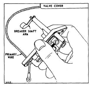
Remove Breaker Box
Remove the two mounting screws, then remove the
breaker box, turning it slightly to clear the arm at inner
end of breaker shaft. See Fig. 54. Breaker points need
not be removed to remove breaker box.
Fig. 54 - Removing Breaker Box Assembly
Remove Breaker Shaft
The breaker shaft can be removed (after breaker points
are removed) by turning the shaft one half turn to clear
the retaining spur at the inside of the breaker box.
Install Breaker Shaft
Insert the breaker shaft with arm upward so arm will
clear the retainer boss. Push the shaft all the way in,
then turn arm downward.
Install Breaker Box
Pull the primary wire through the hole at lower left corner
of breaker box. See that the primary wire rests in the
groove at top end of box: then tighten the two mounting
screws to hold box in place.
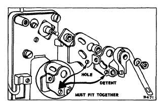
Install Breaker Points
Press in the new oil seal with the metal side out. Put
new breaker plate on top of insulating plate, taking care
that the detent in breaker plate engages hole in
insulating plate. Fasten breaker plate screw only enough
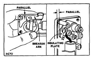
to put a light tension on the plate. See Fig. 55. Adjust
eccentric so that left edge of insulating plate is parallel to
edge of box and tighten screw. Fig. 56. This locates the
breaker plate so that proper gap adjustments may be
made. Turn breaker shaft clockwise as far as possible
and hold in this position. Place new breaker point on
shaft, then the lockwasher and tighten nut down on
lockwasher. Replace spring screw and terminal screw.
Fig. 55 - Breaker Box Assembly
Fig. 56 - Insulating Plate Position
2
15