TM 5-4240-501-14P
IGNITION
FLYWHEEL TYPE-- EXTERNAL BREAKER
MODEL SERIES 193000, 200000, 230000,
243000, 300000, 320000, 19D, 23D
Fig. 25 - Flywheel Ignition External Breaker
Models 193000, 200000, 233000, 243000,
300000, 320000
Replace Breaker Points -
Model Series 193000, 200000, 230000, 243000,
300000, 320000, 19D, 23D
Turn crankshaft until points open to widest gap. This
makes it easier to assemble and adjust points later if
crankshaft is not removed. Remove condenser and
upper and lower mounting screws. Loosen lock nut and
back off breaker point screw. Fig. 26. Reverse process
to install.
Fig. 26 - Breaker Points
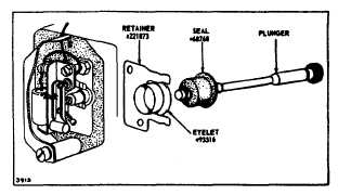
To avoid the possibility of oil leaking past the breaker
point plunger or moisture entering the crankcase
between plunger and bushing, a plunger seal is now
installed on engine models using this ignition system.
Fig. 27. These parts may be added to engines in the
field if contaminated points are experienced.
Fig. 27 - Seal Assembly
EXTREME
CARE
SHOULD
BE
TAKEN
WHEN
INSTALLING SEAL ON PLUNGER, OR SEAL MAY BE
FRACTURED.
NOTE:
Before
mounting
the
breaker-condenser
assembly, apply a sealer such as Permatex" to the
threads of both mounting screws and the adjustment
screw. The sealer prevents oil from leaking into the
breaker point area.
Mount
the
breaker
point
assembly,
then
tighten
adjustment screw until the locknut has pushed the ferrule
as far as possible toward the head of the adjustment
screw. This secures the adjustment screw firmly to the
breaker point.
Adjust and Clean Breaker Points
Turn the crankshaft until the points open to their widest
gap. Turn breaker point adjusting screw points open to
.020" (0.5 mm). Tighten locknut, while holding
adjustment screw, Fig. 26. To clean points turn
crankshaft until points are closed. Insert a piece of
lintless paper and draw the paper between the points.
Open the breaker points to withdraw the paper (so the
paper will not tear and allow a small portion to remain
between the points).
Apply additional sealer at the point at which the primary
wire passes under the breaker cover. This area must be
re-sealed to prevent the entry of dust and moisture. See
Fig. 28.
2
8


