
TM 9-2350-256-20-1
0069 00
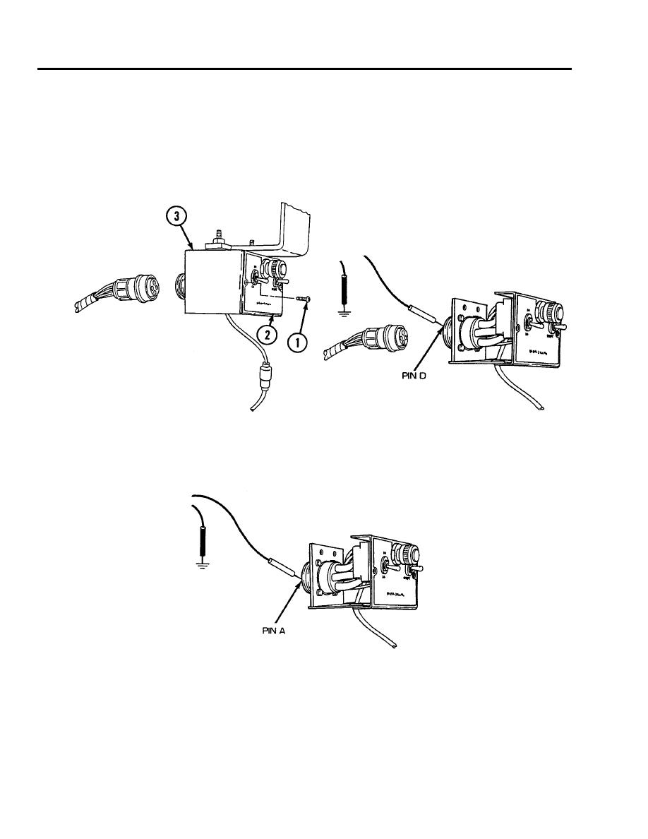
CORRECTIVE ACTION Continued
2.
Reconnect wire 400 of switch panel to head lamps and bulkhead wiring harness to HEATER CON-
TROL box connector. Remove two screws (1) and release personnel heater control box front panel
(2) from personnel heater control box (3). Disconnect heater control box to heater wiring harness
from HEATER CONTROL box. Place red lead of multimeter on pin D of wire 405 and black lead to
ground. Turn MASTER switch on, HEATER CONTROL switch to START, and check for voltage.
Turn MASTER and HEATER CONTROL switches OFF. If voltage is present, go to step 3. If voltage
is not present, replace HEATER CONTROL box (see WP 0161 00).
3.
Place red lead of multimeter on pin A of wire 402 and black lead to ground. Turn MASTER switch on,
HEATER CONTROL switch to START, and check for voltage. Place HEATER CONTROL switch
in RUN position and check for voltage. Turn MASTER and HEATER CONTROL switches OFF. If
voltage is present, go to step 4. If voltage is not present, replace HEATER CONTROL box (see WP
0161 00).
0069 00-4
