
TM 9-2350-256-20-1
0068 00
CORRECTIVE ACTION Continued
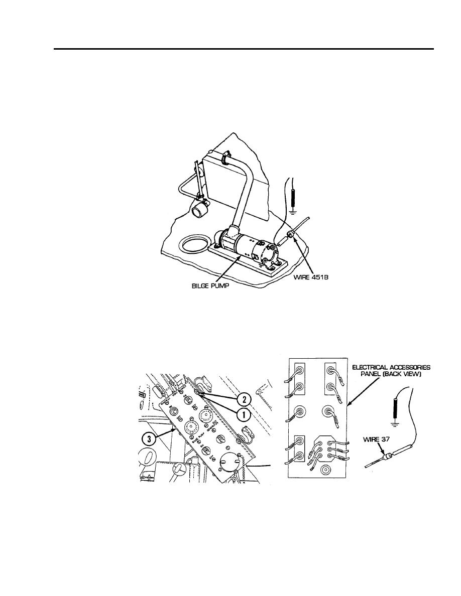
16. Reconnect bilge pump circuit breaker to switch panel lead assembly to bilge pump relay. Disconnect
wire 451B from bilge pump. Place red lead of multimeter in wire 451B and black lead to ground. Turn
MASTER and BILGE PUMP switches ON and check for voltage. Turn MASTER and BILGE PUMP
switches OFF. If voltage is present, replace bilge pump assembly (see WP 0473 00). If voltage is not
present, repair/replace wire 451B of bilge pump circuit breaker to switch panel lead assembly (see WP
0234 00).
17. Remove four screws (1) and four lockwashers (2) and release electrical accessories panel (3). Discon-
nect wire 37 from electrical accessories panel power outlet. Place red lead of multimeter on wire 37
and black lead to ground. Turn MASTER and BILGE PUMP switches ON and check for voltage. Turn
MASTER and BILGE PUMP switches OFF. If voltage is present, replace electrical accessories panel
power outlet (see WP 0158 00). If voltage is not present, repair/replace wire 37 of bilge pump and
generator cutout switch lead assembly (see WP 0232 00).
END OF WORK PACKAGE
0068 00-11/12 blank
