TM 9-2350-256-20-2
0194 00
7.
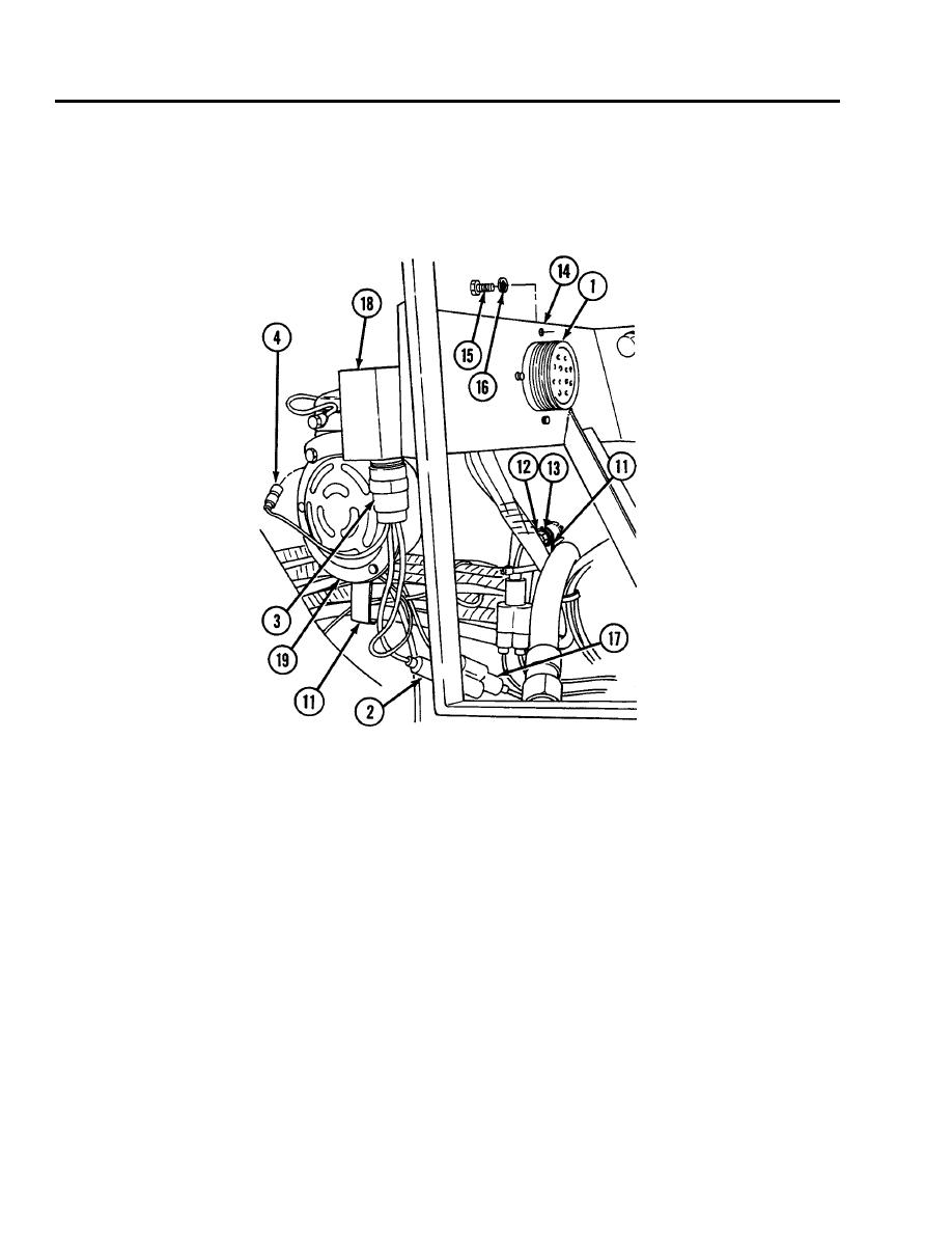
Connect connector (4) to powerpack warning horn assembly (19).
8.
Connect connector (3) to powerpack warning horn (18).
9.
Connect connector (2) to APU control box to foot dimmer switch and bulkhead wiring harness (17).
10. Install connector (1) to gage panel bracket (14) using four lockwashers (16) and four screws (15).
11. Install 19 clamps (11) using lockwasher (13) and screw (12) for each.
NOTE
Follow-on maintenance: Install air cleaner (see WP 0137 00).
END OF WORK PACKAGE
0194 00-6


