SECTION II: HULL COMPONENTS
TM 9-2350-256-20
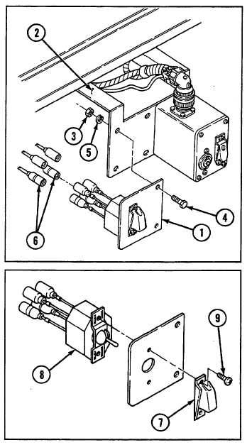
16-5 REPAIR/REPLACE COMMANDER'S PLATE AND SWITCH ASSEMBLY
THIS TASK COVERS
a. Removal
b. Disassembly
c. Assembly
d. Installation
INITIAL SET-UP
Tools:
Parts:
Tool kit, general mechanic's (Appendix C, item 53)
Lockwashers (2) (Appendix G, item 106)
NOTE
Commander's plate and switch assembly is only found in vehicles equipped with an M239 smoke grenade launcher.
a. REMOVAL
1
Remove plate (1) from M239 launcher switch bracket
(2) by removing two nuts (3), two screws (4), and two
lockwashers (5).
2
Tag and disconnect four electrical cables (6).
b. DISASSEMBLY
1
Remove switch guard (7) and switch assembly (8) by
removing two screws (9).
2
Disassemble switch assembly (8) leads (see Chapter 6,
Section VII).
c. ASSEMBLY
1
Assemble switch assembly (8) leads (see Chapter 6,
Section VII).
2
Install switch assembly (8) and switch guard (7) with
two screws (9).
d. INSTALLATION
1
Connect four electrical cables (6). Remove tags.
2
Install plate (1) to M239 launcher switch bracket (2)
with two screws (4), two new lockwashers (5), and two
nuts (3).
16-9 (16-10 blank)