SECTION II: HULL COMPONENTS
TM 9-2350-256-20
SECTION II: HULL COMPONENTS
Para.
Task
Page
16-4
Repair/Replace Driver's Bracket and Switch Assembly ....................................................16-7
16-5
Repair/Replace Commander's Plate and Switch Assembly
.........................................16-9
16-4 REPAIR/REPLACE DRIVER'S BRACKET AND SWITCH ASSEMBLY
THIS TASK COVERS
a. Removal
b. Disassembly
c. Assembly
d. Installation
INITIAL SET-UP
Tools:
Parts:
Tool kit, general mechanic's (Appendix C, item 53)
Lockwashers (2) (Appendix GC, item 104)
Lockwashers (2) (Appendix G, item 108)
Lockwashers (4) (Appendix G, item 127)
Packing, preformed (Appendix G, item 194)
a. REMOVAL
1
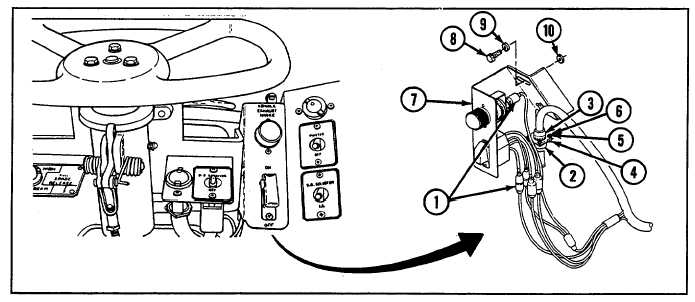
Tag and disconnect five electrical cables (1).
2
Disconnect wiring harness (2).
3
Disconnect wiring harness (3) by removing four screws (4), four lockwashers (5), and four nuts (6).
4 Remove bracket (7) by removing two screws (8), two lockwashers (9), and two flat washers (10).
16-7

