SECTION I: ENGINE COMPONENTS
TM 9-2350-256-20
12
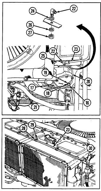
Remove four clamps (28) by removing four screws
(29).
13
Remove tube assembly (23) by disconnecting from
elbow (30).
b.
INSTALLATION
1
Install bulkhead elbow (22) and flat washer (24) to
shroud bracket (25) with new lockwasher (26) and
new locknut (27).
2
Install tube assembly (23) by connecting at bulkhead
elbow (22) and elbow (30).
3
Secure tube assembly (23) with four clamps (28)
and four screws (29).
4
Install tube assembly (20) by connecting to elbow
(21) and bulkhead elbow (22).
5
Secure tube assembly (23) to gear housing cover
(17) with clamp (16), screw (18), and flat washer
(19).
6
Install tube assembly (6) onto left exhaust manifold
tube (15) and secure tube assembly with clamp (12),
bolt (13), and nut (14).
7
Install tube assembly (5) onto right exhaust manifold
tube (11) and secure tube assembly with clamp (8),
bolt (9), and nut (10).
8
Install 45 elbow (3) to tee (4).
9
Install tee (4) between two tube assemblies (5 and 6)
by tightening two nuts (7).
10
Install tube assembly (1) by connecting to 90 elbow
(2) and 450 elbow (3).
WARNING
Move vehicle out of building before attempting to check system for operation/leaks and extinguish
all open flames in the immediate area. Refer to TM 9-2350-256-10 for operating procedures.
11
Check all connections to ensure tightness.
NOTE
Follow-on maintenance: Install engine deck (see paragraph 9-51)
16-5