SECTION I: ENGINE COMPONENTS
TM 9-2350-256-20
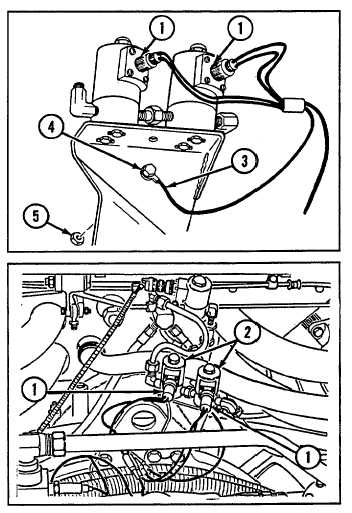
4
Install elbow (18) into remaining solenoid valve (2)
inlet port with connection end of elbow at 4 o'clock
position.
5
Install adapter (10) to elbow (18).
6
Mount solenoid valves (2) on mounting bracket (11)
with four flat washers (15) and four bolts (14).
7
Install mounting bracket (11) with two bolts (12) to
engine lifting eye (13).
8
Position fuel line (8) and tighten nut (9) at adapter
(10).
9
Connect fuel tube assembly (16) to elbow (17).
10
Position fuel tube assembly (16) and tighten nut (6)
at elbow (7).
11
Connect ground lead (3) with screw (4) and new self-
locking nut (5).
12
Connect two cable assemblies (1) to two solenoid
valves (2).
WARNING
Move vehicle out of building before
attempting
to
check
system
for
operation/leaks and extinguish all
open flames in the immediate area.
Refer
to
TM
9-2350-256-10
for
operating procedures.
13
Check all connections to ensure tightness.
NOTE
Follow-on maintenance: Install engine deck (see paragraph 9-51)
16-2 REPLACE FUEL TUBE ASSEMBLIES
THIS TASK COVERS
a. Removal b. Installation
INITIAL SET-UP
Tools:
Parts:
Reference:
Tool kit, general mechanic's
Locknut (Appendix G, item 94)
TM 9-2350-256-10
(Appendix C, item 53)
Lockwasher (Appendix G,
item 120)
Equipment Condition:
Engine deck removed (see
paragraph 9-51)
16-3