CHAPTER 16: MAINTENANCE OF EXHAUST SMOKE GENERATING SYSTEM
TM 9-2350-256-20
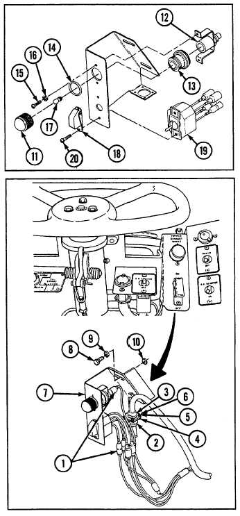
16.4 REPAIR/REPLACE DRIVER'S BRACKET AND SWITCH ASSEMBLY- Continued
b. DISASSEMBLY
1
Unscrew and remove light lens (11).
2
Remove indicator light (12), adapter (13), and
preformed packing (14) by removing two screws (15)
and two lockwashers (16).
3
Remove lamp (17) from indicator light (12) by pressing
in lamp and turning counterclockwise.
4
Remove switch guard (18) and switch assembly (19) by
removing two screws (20).
5
Disassemble switch assembly (19) cables (see Chapter
6, Section VII).
c. ASSEMBLY
1
Assemble switch assembly (19) cables (see Chapter 6,
Section VII).
2
Install switch guard (18) and switch assembly (19) with
two screws (20).
3
Install lamp (17) in indicator light (12) by pressing in
lamp and turning clockwise.
4
Install indicator light (12), adapter (13), and new
preformed packing (14) with two screws (15) and two
new lockwashers (16).
5
Install light lens (11).
d. INSTALLATION
1
Install bracket (7) with two screws (8), two new
lockwashers (9), and two flat washers (10).
2
Connect wiring harness (3) with four screws (4), four
new lockwashers (5), and four nuts (6).
3
Connect wiring harness (2).
4
Connect five electrical cables (1). Remove tags.
16-8