CHAPTER 2: VEHICLE MAINTENANCE INSTRUCTIONS
TM 9-2350-256-20
2-19 ELECTRICAL TROUBLESHOOTING-Continued
APU LOW OIL PRESSURE SYSTEM-Continued
WARNING
Remove all jewelry such as rings, dog
tags, bracelets, etc. If jewelry contacts a
metal surface a direct short may result in
instant
heating
of
tools,
damage
to
equipment,
and
injury
or
death
to
personnel.
C
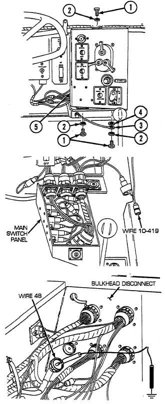
Reconnect APU control box to dimmer switch and
bulkhead wiring harness to APU control box. Remove
three screws (1), three lockwashers (2), ground wire
(3), and flat washer (4), and release main switch panel
(5) from mounting bracket. Disconnect wire 10-419
from Y-connector of switch panel, radio, and bilge
pump to bulkhead wiring harness at main switch panel.
Turn MASTER switch on, and check for voltage. If
voltage is present, repair wire 419 from Y-connector at
main switch panel to APU control box bulkhead wiring
harness. If voltage is not present, go to step D.
D
Reconnect wire 10-419 to Y-connector of switch panel,
radio, and bilge pump to bulkhead wiring harness to
main switch panel. Install main switch panel (5), flat
washer (4), ground wire (3), three lockwashers (2), and
three screws (1) to mounting bracket. Open air inlet
doors (TM 9-2350-256-10). Disconnect wire 48 pin A
from bulkhead to master relay wiring harness. Place
red multimeter lead in socket and black lead to ground.
Turn MASTER switch on and check for voltage. If
voltage is present, repair/replace switch panel, radio,
and bilge pump to bulkhead wiring harness (see
paragraph 6-53). If voltage is not present,
troubleshoot master relay circuit (see paragraph 2-19,
master relay fails to operate).
2-176