SECTION V: TROUBLESHOOTING
TM 9-2350-256-20
WARNING
Remove all jewelry such as rings, dog tags,
bracelets, etc. If jewelry contacts a metal
surface a direct short may result in instant
heating of tools, damage to equipment, and
injury or death to personnel.
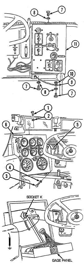
G Reconnect wire 27 at Y-connector. Install main switch
panel (11), flat washer (10), ground lead (9), three
lockwashers (8), and three screws (7) to mounting
brackets. Remove three screws (1), three lockwashers
(2), two screws (3), two lockwashers (4), and ground strap
(5) and release gage panel (6) from mounting brackets.
Disconnect
switch
panel
to
gage
panel
and
miscellaneous switches wiring harness from gage panel.
Place red multimeter on socket K and black lead to
ground. Turn MASTER switch on and check for voltage.
Turn MASTER switch OFF. If voltage is present, go to
step L. If voltage is not present, repair/replace wire 27 of
switch panel to gage panel and miscellaneous switches
wiring harness (see paragraph 6-55 for dual voltage; 6-56
for single voltage).
2-201