SECTION II: PRIMARY, FUEL/WATER SEPARATOR, AND MANIFOLD
TM 9-2350-256-20
HEATER FUEL RLTERS AND RELATED PARTS
WARNING
• Ignition units on this engine are capable of producing extremely high voltage. The output is
sufficient to cause a dangerous electrical shock. Never touch uncovered or live connections.
Ensure MASTER switch is in OFF position prior to removal or maintenance.
• Do not smoke or use open flame when working on fuel system: explosion may occur, causing
severe injury or death.
NOTE
Removal and installation procedures are the same for the ignition unit on each side of the engine.
a. REMOVAL
1
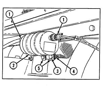
Disconnect two electrical wiring harness
connectors (1) from manifold heater ignition unit
(2).
2
Remove two screws (3) and two self-locking nuts
(4). Remove two clamps (5) and manifold heater
ignition unit (2).
b. INSTALLATION
1
Install manifold heater ignition unit (2) into two
clamps (5) and secure with two screws (3) and two
new self-locking nuts (4).
2
Connect two electrical wiring harness connectors
(1) on manifold heater ignition unit (2).
NOTE
Follow-on maintenance: Install powerplant (see paragraph 3-1)
4-20 REPLACE MANIFOLD HEATER FUEL RETURN SOLENOID VALVE
THIS TASK COVERS
a. Removal
b. Installation
INITIAL SET-UP
Tools:
Equipment Conditions:
Tool kit, general mechanic's (Appendix C, item 53)
• Engine deck removed (see paragraph 9-51)
• MASTER switch turned to OFF position
WARNING
Do not smoke or use open flame when working on fuel system: explosion may occur, causing severe
injury or death.
4-43