SECTION II: PRIMARY, FUEL/WATER SEPARATOR, AND MANIFOLD
TM 9-2350-256-20
HEATER FUEL RLTERS AND RELATED PARTS
4
Install solenoid valve (4) with related fittings on mounting bracket (5) with two flat washers (7) and two
assembled washer bolts (6).
5
Connect fuel solenoid outlet tube (2) and two fuel solenoid inlet tubes (3).
6
Connect electrical wiring harness connector (1).
NOTE
Follow-on maintenance: • Turn MASTER switch to ON position
• Install engine deck (see paragraph 9-51)
4-21 REPLACE/REPAIR MANIFOLD HEATER NOZZLE ASSEMBLY
THIS TASK COVERS
a. Removal
b. Disassembly
c. Assembly
d. Installation
INITIAL SET-UP
Tools:
Parts-Continued:
Tool kit, general mechanic's (Appendix C, item 53)
• Gaskets (2) (Appendix G, item 50)
• Nuts, self-locking (8) (Appendix G, item 166)
Parts:
• Spark plugs (with gasket) (2) (Appendix G,
• Bushing (Appendix G, item 9)
item 267)
WARNING
Do not smoke or use open flame when working on fuel system: explosion may occur, causing severe
injury or death.
a. REMOVAL
NOTE
Removal and installation procedures are the same for both the left and right bank. Right bank
shown.
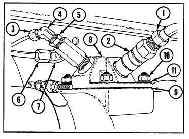
1
Disconnect electrical lead (1) from spark plug (with
gasket) (2).
2
Disconnect fuel inlet hose (3) from fuel inlet elbow
(4). Remove fuel inlet elbow and bushing (5).
3
Disconnect fuel return tube (6) from fuel return
elbow (7). Remove fuel return elbow.
4
Remove manifold heater (8) and gasket (9) by
removing four self-locking nuts (10) and four flat
washers (11). Discard gasket.
4-45