SECTION III: SENDING UNITS, WARNING LlGHT SWITCHES, AND
TM 9-2350-256-20
WARNING HORNS
c. ASSEMBLY
1
Install rheostat (38), using three screws (35), three new lockwashers (37), and three nuts (36).
2
Install cap (32), new lockwasher (34), and screw (33).
3
Install screw (29), new lockwasher (30), and nut (31).
4
Install bracket assembly (21) using two screws (26), two new lockwashers (28), two nuts (27), two loop clamps
(25), two screws (22), two new lockwashers (24), and two nuts (23).
5
Install 3 new gaskets (18) and 3 connectors (17), using 12 screws (19) and 12 new lockwashers (20).
6
Install two diodes (13) using two screws (14), six new lockwashers (16), and two nuts (15).
7
Install relay (10) using eight screws (11) and eight new lockwashers (12).
8
Install new gasket (7) and relay switch cover (6) using 16 new lockwashers (9) and 16 screws (S).
d. CALIBRATION
NOTE
l No calibration is required if the auxiliary power unit or switching relay box is removed and
reinstalled with no change being affected.
l System must not be operated four hours prior to performing this calibration procedure.
1
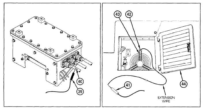
Place multimeter on one volt scale, and connect black lead (39) to wire of circuit 478A (40) at switching relay
box (3) (ie., sharpen tip with file, and puncture circuit 478A insulation).
2
Connect red lead (41) of multimeter onto a piece of extension wire, and connect other end of wire to
mounting screw (42) of APU flywheel guard (43) inside AFU access door (44).
Change 1
6-44.1