TM 9-2350-256-20
CHAPTER 6:
MAINTENANCE OF ELECTRICAL SYSTEMS AND CIRCUITS
6-13 REPLACE/REPAIR SWITCHING RELAY BOX ASSEMBLY (SINGLE VOLTAGE
REGULATOR)-Continued
3
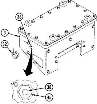
Remove cap assembly (32) from end of switching relay box (3), loosen rheostat locknut (45) with screwdriver,
and turn rheostat (38) fully counterclockwise.
4
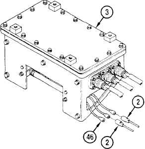
Connect only, the 61A leads (3) of resistor beneath switching relay box (3), leaving 61AC (46) open
5
Start main engine, operate at approximately 1000 rpm and charge batteries for 30 minutes, then turn off
engine.
6
Leave main engine fuel turned off, and crank its starter for three cycles of 15 seconds on and 3 minutes off
7
Start APU, and warm up, unloaded for one minute
8
Turn on generator switch and quickly (within 15 seconds) adjust rheostat for .50 volts on meter before
movement of rheostat no longer produces a voltage change, or voltage begins to decrease. Then turn off APU
generator and engine.
NOTE
If adjustment of rheostat cannot be made to obtain .50 volts, turn off generator and engine, return
reheostat fully counterclockwise, replace a 61A lead on resistor with 61AC lead, then continue with
step 9.
9
Repeat steps 6, 7, and 8 to make final adjustment of rheostat so as to obtain .50 volts on multimeter
10. Tighten rheostat locknut (45), replace cap assembly (32) on switching relay box (3). Disconnect leads (2).
Remove multimeter. System is calibrated.
6-44.2
Change 1