SECTION V: VEHICLE WIRING
TM 9-2350-256-20
b. DISASSEMBLY
Disassemble wiring harness (see Chapter 6, Section VII).
c. ASSEMBLY
Assemble wiring harness (see Chapter 6, Section VII).
d. INSTALLATION
1 Connect connector (4) to personnel heater control box (12).
2 Connect connector (3) to heater fuel pump (11).
3 Install connector (2) using new lockwasher (10) and screw (9).
4 Connect connector (1) to personnel heater (8).
5 Install 16 clamps (5) using new lockwasher (7) and screw (6) for each.
NOTE
Follow-on maintenance: Install heater control box (see paragraph 9-12)
6-88 REPLACE/REPAIR HYDRAULIC OIL TEMPERATURE TRANSMITTER
HOUSING ASSEMBLY WIRING HARNESS (11672366)
THIS TASK COVERS
a. Removal
b. Disassembly
c. Assembly
d. Installation
INITIAL SET-UP
Tools:
Parts:
Equipment Condition:
Tool kit, general mechanic's
Gasket (Appendix G, item 85)
Oil temperature transmitter
(Appendix C, item 53)
Lockwashers (4) (Appendix G,
and switch housing assembly
item 126)
removed (see paragraph 12-10)
WARNING
Be certain MASTER switch is OFF when working on electrical systems to avoid electrical shock or bums.
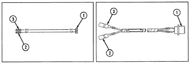
Connector No.
Electrical Lead To:
Wire No.
1
Oil temperature transmitter and housing assembly
663,664
2
Hydraulic oil temperature transmitter
664
3
Hydraulic oil high temperature switch
663
6-235