TM 9-2350-256-34-1
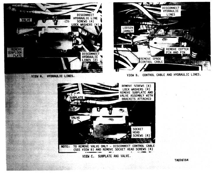
Figure 2-47. Spade subplate and control valve assembly—removal and installation.
g. Spade Cable Control Assembly.
(1) Removal. Remove the spade control cable
as shown in Views F, G, H and I of figure 2-28 and
View B of figure 2-47.
(2) Installation. Install the spade control cable
in reverse order of removal.
(3) Adjustment, Install new cable keeping
jamnuts (View B, fig. 2-47) loose for adjustment.
Center spade control lever and tighten jamnuts. To
adjust lever travel:
(a) Loosen jamnuts on adjustment screws
(View F, fig. 2-28).
(b) Backoff adjustment screws.
(c) Move spade control lever completely
back. Adjust screw until it touches lever and add one
full turn. Tighten jamnut.
(d) Repeat step (c) with lever completely
forward. Adjust front adjustment screw until it
touches lever and add one full turn. Tighten jamnut.
h. Flow Regulating Subplate Assembly. Remove
and install the flow regulating subplate assembly
as shown in figure 2-48.
2 - 8 1