Google+
Facebook
LinkedIn
Twitter
Digg
StumbleUpon
Home
Download PDF
Order CD-ROM
Order in Print
Figure 2-47. Spade subplate and control valve assemblyremoval and installation
Figure 2-49. Boom limit pilot valves-removal and installation
TM-9-2350-256-34-1 Recovery Vehicle Full-Tracked: Medium M88A1 (NSN 2350-00-122-6826) Manual
Page Navigation
88
89
90
91
92
93
94
95
96
97
98
TM 9-2350-256-34-1
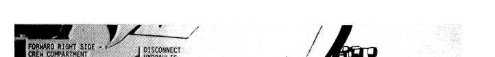
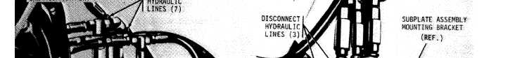
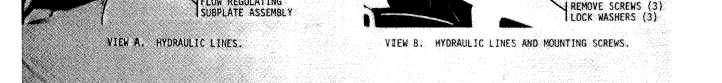
Figure 2-48. Flow regulating subplate assembly–removal and installation.
i. Boom Limit Pilot Valves.
Prior to removal of
as shown in figure 2-49. Refer to TM 9-2350-256-20
the boom limit valves, remove deck grilles 6 and 20
for adjustment instructions.
(fig. 2-2). Remove and install the boom limit valves
2-82
Integrated Publishing, Inc. - A (SDVOSB) Service Disabled Veteran Owned Small Business