TM 9-2350-256-34-1
Section ll. REPAIR OF POWERPLANT
3-4.
Description.
Refer to TM 9-2815-220-34 for description and operation
of the Continental Model AVDS-1790-2DR engine. Refer
to TM 9-2520-215-34 for description and operation of the
Allison-GM Model XT-1410-4 cross-drive transmission.
3-5.
Removal.
Refer to TM 9-2350-256-20 for instructions on removing
the powerplant from the vehicle.
REMOVING / INSTALLING TRANSMISSION
Special Tools:
Sling (Tool ref 141, App B)
NOTE
Discard
all
lockwashers,
lockwires,
cotter pins, packings, gaskets, and
seals. Replace with new parts during
installation.
NOTE
Remove powerplant (page 3-7) from
vehicle before performing separation of
engine and transmission.
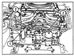
REMOVAL
1
Remove transmission breather tube (1) by
loosening one coupling nut (2) at each end.
3-6.
Disassembly.
a.
Main Engine and Transmission Separation.
For instructions on separating the main engine from the
transmission, refer to the instructions below. If just the
transmission is to be repaired or replaced, it is not
necessary to remove the wiring harness and accessories
from the engine.
b.
Wiring Harness and Accessories. Remove all
accessory items necessary to work on the engine and
transmission (TM 9-2350-256-20). Remove wiring
harnesses and cables as shown in figure 3-2. Figure 3-3
shows the main engine wiring diagram.
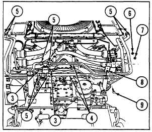
2
Disconnect two electrical harness connectors
(3).
3
Remove four transmission oil cooler lines (4) by
loosening on each, two nuts (5), and removing
two nuts (6), two flat washers (7), two loop
clamps (8), and two screws (9).
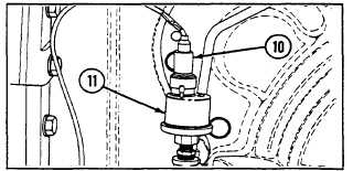
4
Disconnect electrical harness connector (10) at
transmission oil pressure sending unit (11).
3-2 CHANGE 7