TM 9-2350-256-34-2
1
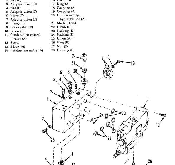
Subplate(A)
15 Retainer(A)
2
Nut(C)
16 Chain(A)
3
Adapter union(C)
17 Ring(A)
4
Nut(C)
18 Coupling(A)
5
Adapter union(C)
19 Coupling(A)
6
Valve(C)
20 Hose assembly,
7
Adapter union(C)
hydraulic line(A)
8
Flange
21 Marker band
9
Lockwasher (B)
22 Elbow(B)
10
Screw(B)
23 Packing(D)
11
Combination control
24 Packing(D)
valve(A)
25 Union(A)
12
Screw
26 Plug(B)
13
Elbow(A)
27 Nut(C)
14
Retainer assembly(A)
28 Bushing(C)
NOTE: The letters in parenthesis refer to figure 3-29 view.
Figure 3-28. Spade subplate and combination control valve assembly-exploded view-disassembly and assembly.
TA171831
CHANGE 4 3-43