TM 9-2350-256-34-2
LEGEND:
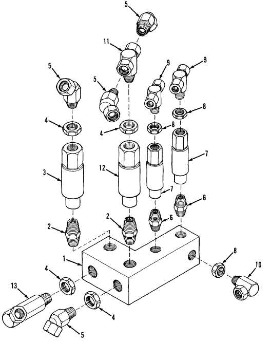
1
Subplate(A)
2
Nipple(D)
3
Flow Regulator(D)
4
Nut(B)
5
Adapter union(B) (C)
6
Nipple(D)
7
Flow regulator(D)
8
Nut(C)
9
Adapter union (C)
10
Adapter union(B)
11
Adapter union (C)
12
Flow regulator(D)
13
Adapter union(B)
NOTE: The letters in parentheses refer to figure 3-31 view.
Figure 3-30. Flow Regulator Subplate Assembly, Exploded View - Disassembly and Assembly.
TA171823
3-46 CHANGE 3