TM 9--2350--292--20--1
0188 00--12
POWERPACK ASSEMBLY REPLACEMENT -- CONTINUED
0188 00
Installation--Continued
WARNING
CAUTION
Do not scratch or damage saddle caps. A defective cap
may cause oil leaks after installation. Remove nicks and
burrs prior to installation.
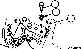
13 Clean saddle cap (21) and screws (19) using dry--cleaning solvent.
14 Apply adhesive uniformly on saddle cap (21) flanges and mounting screws (19).
15 Install saddle caps (21) on both output drives using six screws (19) and six new lockwashers (20). Torque screws
to 83--100 lb--ft (113--136 NSm).
Figure 166
19
20
21
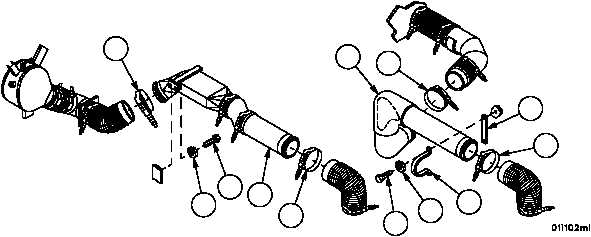
16 Install bar (46), air duct (48) with two screws (43) and two new lockwashers (44). Slide hose ends on duct, tighten
two hose clamps (47).
17 Install left air duct (42) and two hose clamps (41) with two screws (39) and two new lockwashers (40). Slide hose
ends on duct, tighten two hose clamps (41).
Figure 22
41
40
39
42
41
43
44
48
47
46
47
45