TM 9--2350--292--20--1
0188 00--13
POWERPACK ASSEMBLY REPLACEMENT -- CONTINUED
0188 00
Installation--Continued
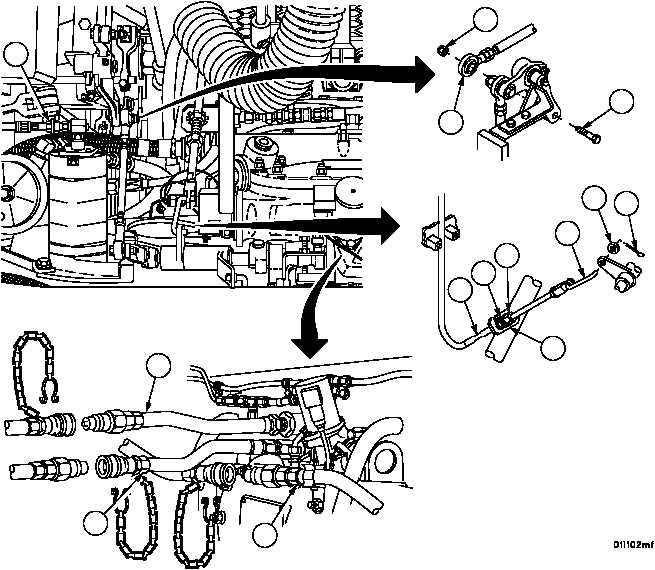
18. Connect fire extinguisher line (38), main fuel line (37) and fuel return hose (36). Secure with connecting ring.
NOTE
Make sure manual fuel control assembly connecting link-
age aligns with hole in throttle linkage before securing nut
and jam nut on engine guide.
19. Install manual fuel shutoff control assembly (34) on engine guide (35) with nut (33) and jam nut (32).
20. Connect manual fuel shutoff connecting link (31) with flat washer (30) and new cotter pin (29).
21. Connect tachometer cable (28).
22. Connect throttle linkage (27) with screw (26) and new self--locking nut (25).
Figure 27
25
26
27
28
29
30
31
32
33
35
38
36
37
34

