TM 9--2350--292--20--1
0220 00--5
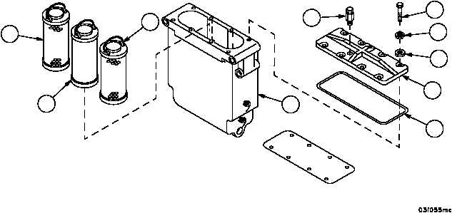
FUEL/WATER SEPARATOR FILTERS REPAIR -- CONTINUED
0220 00
Disassembly
1. Remove seven screws (23), seven lockwashers (24), seven flat washers (25), cover (26) and gasket (27) from
fuel/water separator filter (3). Discard lockwashers and gasket.
2. Remove two outer elements (28) and inner element (29). It may be necessary to turn elements while removing to
get them out easily. Discard outer elements.
3. Remove bleeder valve (2) from cover (26).
Cleaning/Inspecting
WARNING
1. Clean all metal parts, fittings, hose ends, separator (3), bleeder valve (2), cover (26) and inner element (29) with
dry--cleaning solvent. Remove sludge and gum with scraper or stiff brush.
2. Inspect all parts for cracks or damage. Replace any defective parts.
3. Check bleeder valve (2) and attachment point for it in cover (26) to be sure that there is no blockage.
Assembly
1. Install bleeder valve (2) in cover (26).
2. Install inner element (29) and two new outer elements (28).
3. Install new gasket (27) and cover (26) with seven screws (23), seven new lockwashers (24) and seven flat wash-
ers (25) on fuel/water separator filter (3). Torque screws to 144.0 lb--in (16.27 NSm) in accordance with torque
sequence diagram.
Figure 30
3
2
28
29
28
23
24
25
26
27
TORQUE SEQUENCE DIAGRAM
1
2
3
4
5
6
7
8