TM 9--2350--292--20--1
0243 00--14
GAUGE PANEL ASSEMBLY, SUPPORT AND WIRING HARNESS 4W152
REPAIR -- CONTINUED
0243 00
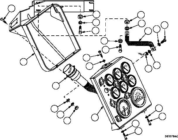
Installation
1. Install speedometer (WP 0694 00) and tachometer (WP 0695 00).
2. Install support (16) on gauge panel assembly (2) with three screws (14) and three new lockwashers (15).
3. Install ground strap (5) and ground lead of wiring harness 4W152 (11) on gauge panel assembly (2) with screw
(12) and two new lockwashers (13).
4. Install wiring harness 4W152 (11) connector J1 in support (16) with four screws (9), four flat washers (10), four
new lockwashers (8) and four nuts (7).
NOTE
Location of gauge panel assembly must be adjusted via
slots on gauge panel mounting bracket such that: A: Full
operation and movement of boom cylinder is possible. B:
Driver’s legs do not contact bottom of gauge panel in nor-
mal seated position.
5. Secure ground strap (5) and gauge panel assembly (2) to hull with four screws (3), five new lockwashers (4) and
four flat washers (6).
Figure 56
9
3
3
4
5
2
6
4
4
6
7
8
10
11
12
13
13
11
14
14
16
15
15
14
15