TM 9--2350--292--20--1
0244 00--2
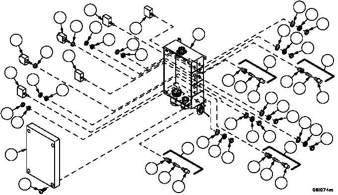
PTO/ACCESSORY PANEL REPAIR -- CONTINUED
0244 00
1. Remove four screws (8) and cover (9) from enclosure (10).
2. Remove PTO/accessory panel’s internal wiring in accordance with Electrical Schematic (FP--17) and remove from
enclosure (10). Discard electrical tiedown straps.
3. Remove four nuts (11), four lockwashers (12), four key washers (13) and four toggle switches (14) from enclosure
(10). Retain attaching hardware for installation.
4. Remove two nuts (15), two lockwashers (16), two key washers (17), two switch boots (18) and two toggle
switches (19) from the enclosure (10). Retain attaching hardware for installation.
NOTE
There are four indicator light assemblies on the PTO/ac-
cessory panel. All four are removed and disassembled in
the same manner. Perform steps 5 and 6 for removal
and disassembly of these light assemblies.
5. Remove nut (20), lockwasher (21) and indicator light holder (22) from enclosure (10). Retain attaching hardware
for installation.
6. Remove lens (23) and LED (24) from socket (25).
8
9
20
21
14
20
21
19
18
14
19
18
20
21
20
21
14
14
10
23
24
25
22
13
12
11
25
24
23
17
16
15
22
11
12
13
15
16
17
23
24
25
22
25
24
23
22
11
12
13
13
12
11