TM 9--2350--292--20--1
0091 00--5
MAIN WINCH FAILS TO OPERATE OR FAILS TO DEVELOP FULL POWER --
CONTINUED
0091 00
CONTINUED FROM STEP C
E
no
yes
CONTINUED ON NEXT PAGE
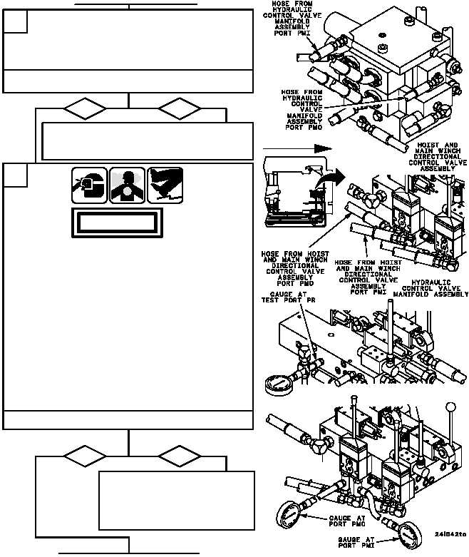
Inspect hoses from hoist and main winch directional
control valve assembly ports PMI and PMO to
hydraulic control valve assembly manifold assembly
ports PMI and PMO for loose connections,
restrictions, and damage.
F
no
yes
1. Remove hydraulic control valve manifold assembly
shields (WP 0519 00).
2. Install 0--4000 psi testing gauge assembly in
hydraulic control valve manifold assembly port PR.
3. Install 0--4000 psi testing gauge assembly with
1/4--inch tee between hydraulic control valve
manifold assembly port PMO and attaching hose.
4. Install 0--4000 psi testing gauge assembly with
1/4--inch tee between hydraulic control valve
manifold assembly port PMI and attaching hose.
5. Start main engine, energize hydraulics, and set
engine speed to 1800 rpm (TM 9--2350--292--10).
6. Payout main winch and record gauge readings.
7. Inhaul main winch and record gauge readings.
8. Shut down hydraulics and main engine
(TM 9--2350--292--10).
If PMO and PMI port pressure is
less than 385 psi and PR pressure
is 385--470 psi, notify Direct Sup-
port Maintenance. If PR pressure
is less than 385 psi, go to Step H.
Are all pressures 385--470 psi?
Tighten loose connections. Remove restrictions.
If restrictions cannot be removed or if damaged,
replace WP 0573 00). Verify fault is corrected.
Are connections tight and are hoses free of restrictions
and damage?
FORWARD
WARNING