TM 9--2350--292--20--1
0092 00--2
MAIN WINCH CREEPS WITH CONTROL IN NEUTRAL -- CONTINUED
0092 00
B
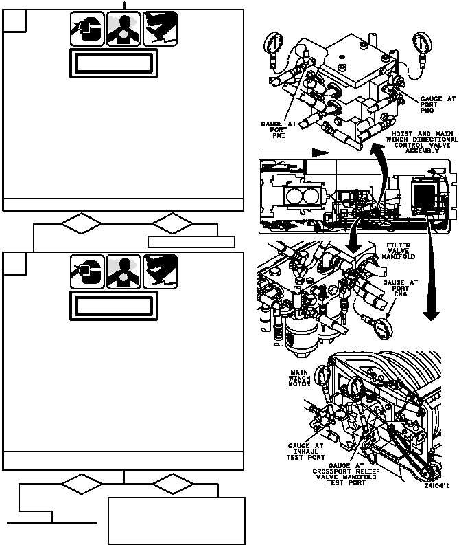
1. Install 0--4000 psi testing gauge assembly with
1/4--inch tee between port PMO of hoist and main
winch directional control valve assembly and
attaching hose.
2. Install 0--4000 psi testing gauge assembly and
1/4--inch tee between port PMI of hoist and main
winch directional control valve assembly and
attaching hose.
3. Start main engine, energize hydraulics, and set
engine speed to 1800 rpm (TM 9--2350--292--10)
4. Shut down hydraulics and main engine
(TM 9--2350--292--10).
C
no
yes
1. Remove gauges from hoist and main winch
directional control valve assembly.
2. Install 0--300 psi dial pressure gauge in filter valve
manifold port CH4.
3. Install 0--5000 psi dial pressure gauge in the main
winch motor crossport relief valve manifold test port
and install 0--5000 psi dial pressure gauge in main
winch motor inhaul test port.
4. Start main engine, energize hydraulics, and set
engine speed to 1800 rpm
(TM 9--2350--292--10). Record gauge pressures.
5. Shut down hydraulics and main engine
(TM 9--2350--292--10).
Replace hoist and main winch
directional control valve
assembly (WP 0556 00).
Verify fault is corrected.
Are pressure readings 140 psi or less?
Are both gauge readings less than 50 psi?
CONTINUED FROM STEP A
CONTINUED ON
NEXT PAGE
WARNING
WARNING
no
yes
Go to Step D.
FORWARD