TM 9--2350--292--20--1
0181 00--4
PAYOUT LIMIT INDICATOR FAILS TO LIGHT WHEN LESS THAN FOUR
WRAPS OF WIRE ROPE ARE LEFT ON DRUM -- CONTINUED
0181 00
G
Is continuity present?
CONTINUED FROM STEP C AND F
no
yes
CONTINUED ON NEXT PAGE
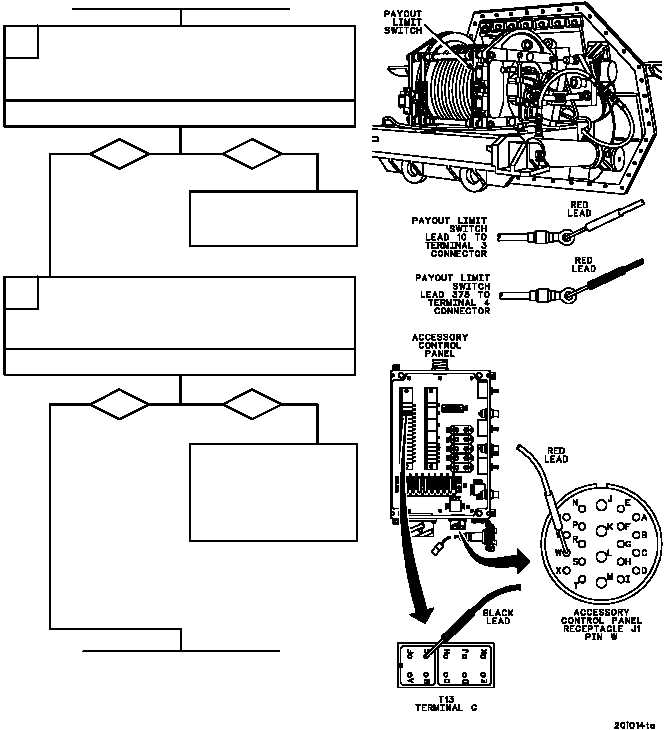
Place one multimeter lead on payout limit
switch terminal 3 connector and other lead
on payout limit switch terminal 4 connector.
Check for continuity.
Replace payout limit
switch (WP 0501 00).
Verify fault is corrected.
H
Is continuity present?
no
yes
Place one multimeter lead on accessory con-
trol panel receptacle J1 pin W and other lead
on terminal junction T13 terminal G. Check
for continuity.
Repair (WP 0290 00) or
replace (WP 0244 00)
lead 375 from recep-
tacle to terminal junction
T13 terminal G. Verify
fault is corrected.