TM 9--2350--292--20--1
0013 00--1
BATT/GEN GAUGE READS IN YELLOW OR LOWER RED WITH APU
RUNNING AND APU GEN SWITCH ON.
0013 00
THIS WORK PACKAGE COVERS:
Batt/Gen Gauge Reads In Yellow Or Lower Red With APU Running And APU GEN Switch On.
INITIAL SETUP:
Tools and Special Tools
General mechanic’s tool kit (item 1, WP 0717 00)
Multimeter (item 84, WP 0717 00)
Personnel Required
Two
Equipment Conditions
APU OFF (TM 9--2350--292--10)
Vehicle MASTER switch OFF (TM 9--2350--292--10)
APU cover removed (WP 0413 00 )
System selector lever set to MAIN
(TM 9--2350--292--10)
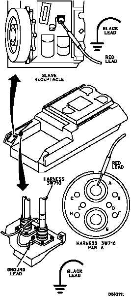
Is 28 V dc present?
1. Turn MASTER switch ON (TM 9--2350--292--10).
2. Start APU (TM 9--2350--292--10).
3. Place multimeter red lead on center conductor of
slave receptacle and black lead to ground.
Check for voltage.
4. Shut off APU (TM 9--2350--292--10).
5. Turn MASTER switch OFF
(TM 9--2350--292--10).
no
yes
Is 28 V dc present?
Go to WP 0085 00.
no
yes
A
1. Remove splash cover protecting voltage regulator
(WP 0239 00).
2. Disconnect harness 3W710 from APU voltage
regulator, but do not remove ground lead.
3. Turn MASTER switch ON (TM 9--2350--292--10).
4. Start APU (TM 9--2350--292--10).
5. Place multimeter red lead on harness 3W710 pin
A and black lead to ground. Check for voltage.
6. Shut off APU (TM 9--2350--292--10).
7. Turn MASTER switch OFF
(TM 9--2350--292--10).
Repair (WP 0290 00) or replace
(WP 0312 00) harness 3W710.
Verify fault is corrected.
B
CONTINUED ON NEXT PAGE
WARNING
Remove rings, bracelets, wristwatches,
and neck chains before working on any
vehicle. Jewelry can catch on equip-
ment and cause injury, or may short
across an electrical circuit and cause
severe burns or electrical shock.