TM 9--2350--292--20--1
0013 00--5
BATT/GEN GAUGE READS IN YELLOW OR LOWER RED WITH APU
RUNNING AND APU GEN SWITCH ON -- CONTINUED
0013 00
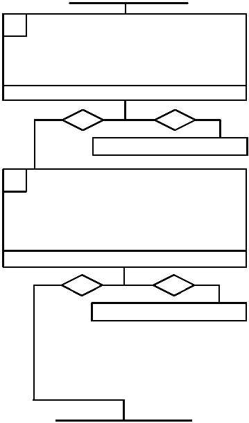
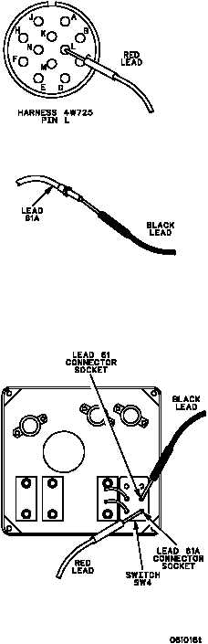
1. Open APU control box (WP 0247 00).
2. Disconnect lead 61A from switch SW4.
3. Place one multimeter lead on harness 4W725
receptacle pin L and other lead on lead 61A
connector. Check for continuity.
I
no
yes
CONTINUED ON NEXT PAGE
CONTINUED FROM STEP H
Is continuity present?
Notify Direct Support Maintenance.
1. Disconnect lead 61 from APU GEN switch.
2. Turn APU GEN switch ON
(TM 9--2350--292--10).
3. Place one multimeter lead in APU GEN switch
lead 61 connector socket and other lead in lead
61A APU GEN switch connector pin socket.
Check for continuity.
no
yes
J
Notify Direct Support Maintenance.
Is continuity present?