TM 9--2350--292--20--2
0641 00--3
AUXILIARY POWER UNIT RELAY AND MOUNTING BRACKET
REPLACEMENT (HATZ) -- CONTINUED
0641 00
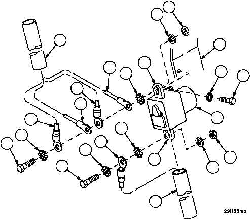
Installation
1. Apply adhesive (item 29, WP 0716 00) to two screws (26).
2. Install relay (28) on mounting bracket (29) with two screws (26) and two new lockwashers (27).
3. Place a four--inch piece of insulation sleeving (30) over lead assembly 3W706 (15) then install lead assembly on
relay terminal A1 (16) with screw (11), two new lockwashers (12), new lockwasher (13) and nut (14).
4. Place a four--inch piece of insulation sleeving (31) over wiring harness 3W711 wire 66 (21), wire N (22) and wiring
harness 3W730 wires 134 (23) and wire 135A (24), then install wires on relay terminal A2 (25) with screw (17),
two new lockwashers (18), new lockwasher (19) and nut (20).
5. Apply adhesive (item 81, WP 0716 00) to relay terminals A1 and A2 (16 and 25) and attaching hardware.
6. Slide insulation sleeving over relay terminals A1 and A2 (16 and 25) and attaching hardware. Shrink insulation
sleeving using electrical heat gun.
20
11
12
15
12
16
13
14
17
18
19
21
18
22
23
24
27
26
25
28
29
30
31