TM 9--2350--292--20--2
0640 00--3
AUXILIARY POWER UNIT RELAY AND MOUNTING BRACKET
REPLACEMENT -- CONTINUED
0640 00
Installation
NOTE
Perform step 1 only if relay mounting bracket has been
removed; otherwise, proceed to step 2.
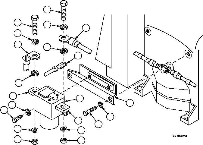
1. Install mounting bracket (27) on APU assembly with two screws (28) and two new lockwashers (29).
2. Install relay (26) on mounting bracket (27) with two screws (24) and two new lockwashers (25).
3. Install lead assembly 3W706 (15) on relay terminal A1 (16) with screw (11), two new lockwashers (12), new lock-
washer (13) and nut (14).
4. Install wiring harness 3W711 wire 66 (21) and wire N (22) on relay terminal A2 (23) with screw (17), two new lock-
washers (18), new lockwasher (19) and nut (20).
Figure 345
11
12
12
13
14
23
24
25
26
27
28
29
15
16
20
19
22
18
21
18
17

