TM 9--2350--292--20--2
0638 00--2
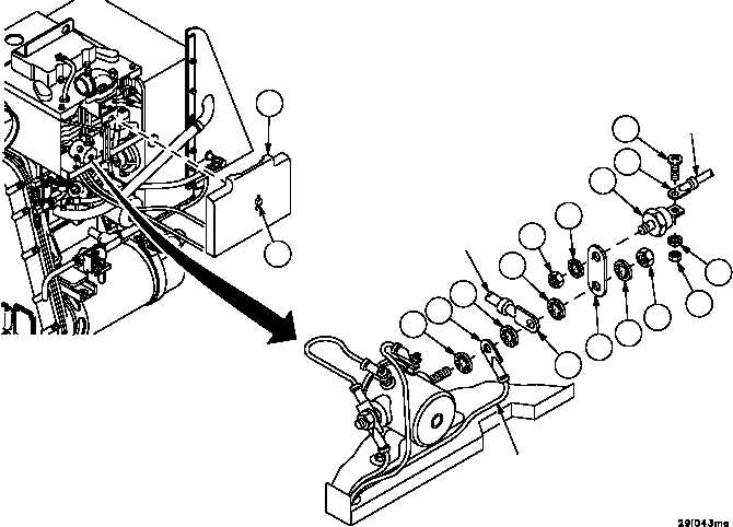
AUXILIARY POWER UNIT DIODE AND MOUNTING PLATE REPLACEMENT --
CONTINUED
0638 00
Installation
1. Install two wires (12 and 13), plate (link) (14), four new lockwashers (11) and nut (10) on relay terminal.
2. Install anode (stud end) of diode (6) on plate (link) (14) with new lockwasher (9) and nut (8).
3. Connect wire (7) to cathode (terminal end) of diode (6) with screw (3), new lockwasher (4) and nut (5).
4. Apply adhesive to all exposed electrical terminals.
5. Install panel (2) and tighten captive screw (1).
Figure 344
2
1
1113
11
12
11
3
7
6
9
8
14
11
10
5
4
(WIRE R)
(WIRE S)
(WIRE 65)
NOTE
FOLLOW--ON MAINTENANCE:
Install APU in vehicle (WP 0587 00)
END OF TASK