TM 9--2350--292--20--2
0376 00--1
BRAKE MODULATING VALVE ASSEMBLY REPAIR (OLD CONFIGURATION)
0376 00
THIS WORK PACKAGE COVERS:
Disassembly, Assembly
INITIAL SETUP:
Tools and Special Tools
General mechanic’s tool kit (item 1, WP 0717 00)
Torque wrench (item 2, WP 0717 00)
Retaining ring pliers set (item 15, WP 0717 00)
Materials/Parts
Lockwashers (6) (item 37, WP 0718 00)
Safety goggles (item 93, WP 0716 00)
Retaining rings (4) (item 451, WP 0718 00)
Lubricant (item 3, WP 0716 00)
Lockwashers (2) (item 9, WP 0718 00)
Equipment Conditions
Vehicle parked on level surface with tracks blocked
and brakes released (TM 9--2350--292--10)
Subfloor plates #14 and #16 removed (WP 0454 00)
Hydraulic hoses disconnected from modulating valve
assembly (WP 0360 00)
Shaft and brake pedal return spring disconnected from
modulating valve assembly (WP 0366 00)
Brake hydraulic cylinder removed (WP 0370 00)
References
TM 9--2350--292--10
WARNING
WARNING
Do not work on hydraulic lines or fittings when system is
pressurized. Hydraulic fluid under pressure can cause
personnel injury. Depressurize brake system by stepping
on the brake pedal several times to bleed off the hydrau-
lic pressure. Make sure brake pressure gauge indicates
zero.
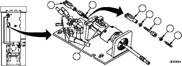
Disassembly
1. Loosen nut (1), remove clevis assembly (2) and nut (1) from modulating valve assembly (3).
2. Remove nut (4) and rod (5) from clevis assembly (2).
3. Loosen nut (6), remove rod end clevis (7) and nut (6) from ball joint (8).
Figure 170
FORWARD
1
2
3
7
6
8
4
5