TM 9--2350--292--20--2
0375 00--1
POWER BOOST MANIFOLD AND PLATE REPAIR (NEW CONFIGURATION
WITH BRAKE MODULATION)
0375 00
THIS WORK PACKAGE COVERS:
Removal, Disassembly, Assembly, Installation
INITIAL SETUP:
Tools and Special Tools
General mechanic’s tool kit (item 1, WP 0717 00)
Materials/Parts
Lockwashers (4) (item 35, WP 0718 00)
Safety goggles (item 93, WP 0716 00)
Equipment Conditions
Vehicle parked on a level surface with tracks blocked
and brakes released (TM 9--2350--292--10)
Equipment Conditions -- Continued
Hydraulic hoses disconnected from power boost
manifold assembly and hydraulic brake cylinder
(WP 0362 00).
Disconnect rod end assembly (WP 0364 00) and
brake cable assembly (WP 0369 00).
Disconnect return spring assembly from pillow block
shaft and lever (WP 0367 00).
References
TM 9--2350--292--10
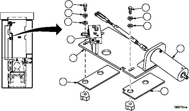
Removal
1. Remove four screws (1), four lockwashers (2) and four flat washers (3) from plate assembly (4). Discard lock-
washers.
NOTE
Quantity of plates may vary. Note quantity and location of
plates removed to aid in installation.
2. Remove plate assembly (4) and any plates (5 and 6) that are present.
Disassembly
1. Remove power boost manifold assembly (7) (WP 0380 00).
2. Remove brake hydraulic cylinder assembly (8) (WP 0371 00).
3. Inspect parts for damage and replace as required.
FORWARD
1
2
3
1
2
3
5
6
7
4
8