TM 9--2350--292--20--2
0376 00--2
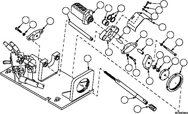
BRAKE MODULATING VALVE ASSEMBLY REPAIR (OLD CONFIGURATION) --
CONTINUED
0376 00
Disassembly--Continued
4. Remove two screws (9), two lockwashers (10), two flat washers (11) and shield (12) from modulating valve (3).
Discard lockwashers.
5. Loosen two nuts (13). Screw disc (14) forward on threaded rod (15).
6. Remove threaded rod (15), disc (14), spanner plate (16) and two nuts (13) from modulating valve assembly (3).
NOTE
Do not remove bushing unless worn or damaged.
7. Remove two nuts (13), disc (14) and bushing (17), if damaged, from threaded rod (15).
8. Remove two screws (18), two lockwashers (19), flange (20) from modulating valve assembly (3). Discard lock-
washers.
9. Remove two screws (21), two lockwashers (22), flange (23), two spacers (24) and modulating valve assembly (3)
from power boost manifold and modulating valve plate (25). Discard lockwashers.
10. Remove two screws (26), two lockwashers (27), flange (28), pushrod (29), support assembly (30) and two
spacers (31) from power boost manifold and modulating valve plate (25). Discard lockwashers.
WARNING
11. Remove four retaining rings (32) and two bearings (33) from support assembly (30). Discard retaining rings.
12. Inspect parts for damage and replace as required.
Figure 171
18
19
20
31
3
25
33
32
9
10
11
12
30
29
28
24
22
21
26
27
16
14
13
13
17
15
23