TM 9--2350--292--20--2
0403 00--5
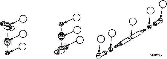
STEERING CONTROL LINKAGE (CREW COMPARTMENT) REPAIR --
CONTINUED
0403 00
Disassembly
NOTE
All tubes, rods and connecting link assemblies are disas-
sembled in the same manner.
1. Loosen two nuts (55) on threaded rod, tube or connecting link (56).
2. Remove bearings or clevis (57) from threaded rod, tube or connecting link (56).
3. Remove two nuts (55) from threaded rod, tube or connecting link (56).
4. Remove retaining ring (58) and bearing (33) from bearing housing (11). Discard retaining ring.
5. Remove retaining ring (59) and bearing (21) from bearing housing (19). Discard retaining ring.
6. Inspect parts for damage and replace as required.
Assembly
1. Install bearing (21) with new retaining (59) into bearing housing (19).
2. Install bearing (33) with new retaining ring (58) into bearing housing (11).
NOTE
All tubes, rods and connecting link assemblies are
assembled in the same manner.
Do not tighten nuts on tubes, rods and connecting link
assemblies during assembly, nuts will be tightened during
adjustment.
3. Install two nuts (55) on connecting link, tube or threaded rod (56).
4. Install two bearings or clevis (57) on connecting link, tube or threaded rod (56).
Figure 191
21
59
58
33
11
57
55
56
19
55
57