TM 9--2350--292--20--2
0403 00--1
STEERING CONTROL LINKAGE (CREW COMPARTMENT) REPAIR
0403 00
THIS WORK PACKAGE COVERS:
Removal, Disassembly, Assembly, Installation
INITIAL SETUP:
Tools and Special Tools
General mechanic’s tool kit (item 1, WP 0717 00)
Retaining pliers set (item 15, WP 0717 00)
Materials/Parts
Lockwashers (12) (item 2, WP 0718 00)
Lockwasher (item 27, WP 0718 00)
Cotter pin (item 19, WP 0718 00)
Retaining rings (2) (item 28, WP 0718 00)
Welding electrodes (AR) (item 9, WP 0716 00)
Equipment Conditions
Vehicle parked on level ground with tracks blocked
and parking brake set (TM 9--2350--292--10)
Subfloor plates #7, #19 and #24 removed
(WP 0454 00)
Gauge panel removed (WP 0243 00)
Driver’s seat removed (WP 0461 00)
Vehicular tool box rack, oddment tray and bracket
removed (WP 0480 00)
Left side air cleaner assembly removed (WP 0208 00)
References
TM 9--2350--292--10
Removal
WARNING
Vehicle can move when steering linkage are disconnecte-
Park vehicle on level ground and block vehicle tracks.
Failure to comply may result in equipment damage or
personnel injury or death.
NOTE
All levers, brackets and bell cranks are provided with a
1/8 in. alignment hole to aid in proper alignment during
installation. Pin levers, brackets or bell cranks not being
removed, before disconnecting components.
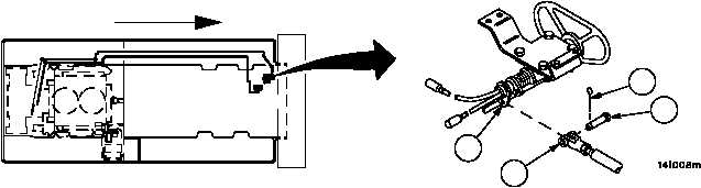
1. Remove cotter pin (1) and straight headed pin (2), disconnect connecting link assembly (3) from steering control
assembly (4). Discard cotter pin.
Figure 191
FORWARD
2
1
3
4