TM 9--2350--292--20--2
0404 00--4
STEERING CONTROL LINKAGE (ENGINE COMPARTMENT) REPAIR --
CONTINUED
0404 00
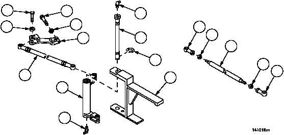
Removal--Continued
16. Remove lubrication fitting (38) from pin (39).
WARNING
17. Remove retaining ring (40) from pin (39). Discard retaining ring.
18. Remove pin (39) and bell crank (34) from mounting bracket (41).
19. Remove lubrication fitting (42) from pin (39).
20. Remove screw (43) and lockwasher (44), disconnect connecting link assembly (37) from remote control lever
(45). Discard lockwasher.
21. Remove screw (46), lockwasher (47) and remote control lever (45) from transmission. Discard lockwasher.
WARNING
22. Clean all parts with dry--cleaning solvent.
Disassembly
NOTE
All tubes, threaded rods, studs and connecting link as-
semblies are disassembled in the same manner.
1. Loosen two nuts (48) on tube, threaded rod, stud or connecting link (49).
2. Remove two bearings or clevis (50) from tube, threaded rod, stud or connecting link (49).
3. Remove two nuts (48) from tube, threaded rod, stud or connecting link (49).
4. Inspect parts for damage and replace as required.
Figure 194
43
44
46
47
45
37
34
38
41
40
39
42
50
48
49
50
48