TM 9--2350--292--20--2
0406 00--4
SHIFTING CONTROL LINKAGE (CREW COMPARTMENT) REPAIR --
CONTINUED
0406 00
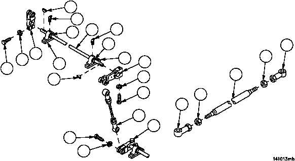
Disassembly
1. Remove screw (41), lockwasher (42) and stud assembly (13) from remote control lever (29). Discard lockwasher.
NOTE
Each shift shaft with two bearing units and two remote
control levers is removed from vehicle as an assembly.
Each shift shaft assembly is disassembled and as-
sembled in the same manner. This task dissembles and
assembles only one shift shaft assembly.
2. Remove two screws (43), two lockwashers (44), two remote control levers (9 and 12) and two woodruff keys (45)
from shift shaft (18). Discard lockwashers.
3. Remove two lubrication fittings (19) from two bearing units (17).
4. Loosen four set screws (46) and remove two bearing units (17) from shift shaft (18).
NOTE
All tubes, threaded rods and connecting link assemblies
are disassembled in the same manner.
5. Loosen two nuts (47) on tube, threaded rod or connecting rod (48).
6. Remove two bearings or clevis (49) from tube, threaded rod or connecting link (48).
7. Remove two nuts (47) from tube, threaded rod or connecting link (48)
8. Inspect parts for damage and replace as required.
Figure 192
49
47
48
47
49
9
44
45
19
19
18
43
44
12
45
41
42
13
29
17
17
46
46
43