TM 9--2350--292--20--2
0406 00--1
SHIFTING CONTROL LINKAGE (CREW COMPARTMENT) REPAIR
0406 00
THIS WORK PACKAGE COVERS:
Removal, Disassembly, Assembly, Installation
INITIAL SETUP:
Tools and Special Tools
General mechanic’s tool kit (item 1, WP 0717 00)
Materials/Parts
Lockwashers (16) (item 2, WP 0718 00)
Lockwashers (2) (item 38, WP 0718 00)
Cotter pins (2) (item 15, WP 0718 00)
Welding electrodes (AR) (item 9, WP 0716 00)
Equipment Conditions
Vehicle parked on level ground with tracks blocked
and parking brake set (TM 9--2350--292--10)
Subfloor plates #19 and #24 removed (WP 0454 00)
Driver’s seat raised (TM 9--2350--292--10)
Vehicular tool box rack, oddment tray and bracket
removed (WP 0480 00)
Left side air cleaner assembly removed (WP 0208 00)
References
TM 9--2350--292--10
Removal
WARNING
Vehicle can move when shifting control linkage is discon-
nectePark vehicle on level ground and block vehicle
tracks. Failure to comply may result in personnel death
or injury or damage to the equipment.
NOTE
All levers, brackets and bell cranks are provided with
1/8--in. alignment hole to aid in proper alignment during
installation. Pin levers, brackets or bell cranks not being
removed, before disconnecting components.
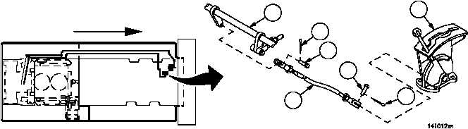
1. Remove two cotter pins (1), two straight headed pins (2) and threaded rod assembly (3) from shift control assem-
bly (4) and locking bar (5). Discard cotter pins.
Figure 192
FORWARD
3
2
1
4
2
1
5