TM 9--2350--292--20--2
0405 00--3
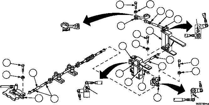
STEERING CONTROL LINKAGES ADJUSTMENT -- CONTINUED
0405 00
Adjustment--Continued
9. Remove screw (17) and lockwasher (18), disconnect tube assembly (19) from bell crank (16). Discard lockwasher.
10. Loosen two nuts (20), adjust tube assembly (19) until bell crank (21) can be pinned. Tighten two nuts (20).
11. Connect tube assembly (19) to bell crank (16) with screw (17) and new lockwasher (18).
12. Remove screw (22) and lockwasher (23), disconnect tube assembly (24) from bell crank (21). Discard lockwasher.
13. Loosen two nuts (25), adjust tube assembly (24) until bell crank (26) can be pinned. Tighten two nuts (25).
14. Connect tube assembly (24) to bell crank (21) with screw (22) and new lockwasher (23).
15. Remove screw (27) and lockwasher (28), disconnect tube assembly (29) from bell crank (30). Discard lockwasher.
16. Loosen two nuts (31), adjust tube assembly (29) until bell crank (30) can be pinned. Tighten two nuts (31).
17. Make sure remote control lever (5) is in neutral position (pointing to center mark on transmission), loosen two nuts
(32) and adjust rod assembly (4) until remote control lever (5) and rod assembly (4) can be connected. Tighten
two nuts (32).
18. Connect rod assembly (4) to remote control lever (5) with screw (2) and new lockwasher (3).
19. Remove welding electrodes from bell cranks.
Figure 193
2
3
5
PIN
PIN
4
PIN
17
18
19
16
20
32
32
30
27
28
26
31
29
23
21
25
24
25
22