TM 9--2350--292--20--2
0406 00--3
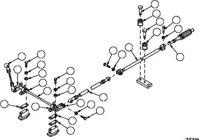
SHIFTING CONTROL LINKAGE (CREW COMPARTMENT) REPAIR --
CONTINUED
0406 00
Removal--Continued
6. Remove four screws (21), four lockwashers (22) and four flat washers (23) from two bearing units (24). Discard
lockwashers.
7. Remove screw (25) and lockwasher (26) from remote control lever (27) and tube assembly (28). Discard lock-
washer.
8. Remove stud assembly (13), two remote control levers (27 and 29), two bearing units (24) and shift shaft (30)
from vehicle as an assembly.
NOTE
Note position of angle bracket during removal to aid in
installation.
9. Remove angle bracket (31) and two spacers (32) from two hull supports.
10. Remove screw (33), lockwasher (34) and tube assembly (28) from connecting link assembly (35). Discard lock-
washer.
11. Remove six screws (36) and six rollers (37) securing connecting link assembly (35) to vehicle hull.
12. Remove screw (38) and lockwasher (39), disconnect connecting link assembly (35) from threaded rod assembly
(40). Discard lockwasher.
Figure 192
21
21
22
22
23
23
24
24
32
32
31
25
26
27
28
13
29
30
33
34
35
36
36
37
37
38
39
40