TM 9--2350--292--20--2
0405 00--2
STEERING CONTROL LINKAGES ADJUSTMENT -- CONTINUED
0405 00
Adjustment--Continued
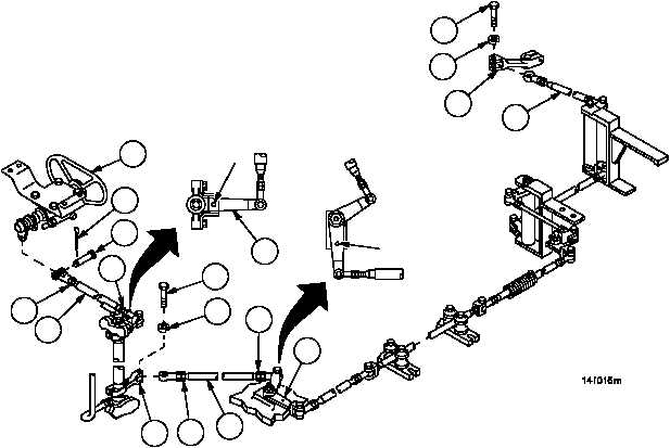
2. Remove screw (2) and lockwasher (3), disconnect rod assembly (4) from remote control lever (5) at transmission.
Discard lockwasher.
3. Remove cotter pin (6) and straight headed pin (7), disconnect connecting link (8) from steering control assembly
(1). Discard cotter pin.
NOTE
All steering control rod and tube assemblies are adjusted
in the same manner. Loosen two nuts and turn rod or
tube assembly, one direction to make it shorter, or the
other direction to make it longer. Both ends must be ad-
justed equally.
4. Loosen two nuts (9), adjust connecting link (8) until steering control assembly (1) is in center (no steer) position
and bell crank (10) can be pinned. Tighten two nuts (9).
5. Connect connecting link (8) to steering control assembly (1) with straight headed pin (7) and new cotter pin (6).
6. Remove screw (11) and lockwasher (12), disconnect tube assembly (13) from remote control lever (14). Discard
lockwasher.
7. Loosen two nuts (15), adjust tube assembly (13) until bell crank (16) can be pinned. Tighten two nuts (15).
8. Connect tube assembly (13) to remote control lever (14) with screw (11) and new lockwasher (12).
Figure 191
1
6
7
9
9
8
2
3
4
5
PIN
PIN
10
16
15
13
15
14
12
11