TM 9--2350--292--20--2
0461 00--8
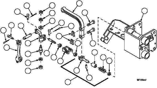
DRIVER’S AND MECHANIC’S SEAT REPAIR -- CONTINUED
0461 00
Disassembly--Continued
30. Remove cotter pin (88), pin (89) and remote control lever (51). Discard cotter pin.
31. Remove cotter pin (90), pin (91) and rod (92). Discard cotter pin.
32. Remove cotter pin (93) and pin (94) from bell crank (95). Discard cotter pin.
33. Remove nut (96), lockwasher (97), flat washer (98) and bell crank (95) from adjusting assembly (67). Discard
lockwasher.
34. Remove nut (99), lockwasher (100) and shouldered stud (101) from adjusting assembly (67). Discard lockwasher.
35. Remove two X--washers (102), two pins (103), lever (104) and clevis assembly (105) from adjusting assembly
(67). Discard X--washers.
36. Remove headless grooved pin (106), flat washer (107), spring (108) and spacer (109) from clevis end (110). Dis-
card headless grooved pin.
37. Remove nut (111), clevis (112) and nut (113) from shaft (114).
38. Inspect parts for damage and replace as required.
51
89
92
91
90
96
97
98
94
93
102
111
104
103
103
109
108
107
106
110
105
113
114
99
100
101
95
67
112
88