TM 9--2350--292--20--2
0356 00--5
BRAKE LINKAGE ALIGNMENT, ADJUSTMENT AND BLEEDING
(NEW CONFIGURATION) -- CONTINUED
0356 00
Alignment -- Continued
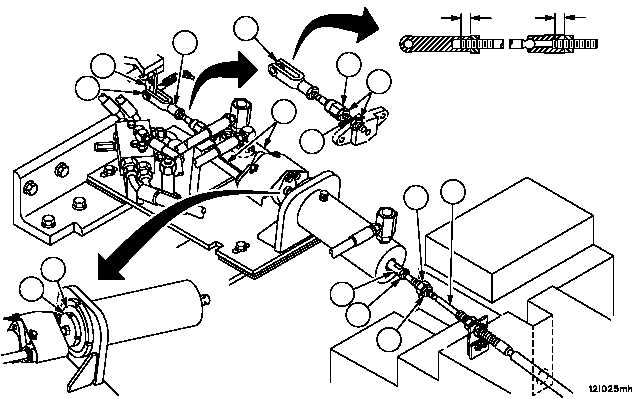
23. Disconnect rod assembly (18) from lever assembly (19) (WP 0366 00).
24. Loosen two nuts (34 and 35) and remove ball joint (36) from rod assembly (37) and brake cable assembly (2).
25. Ensure that disc (25) is resting against the face of brake cylinder (26). If disk (25) does not return to face of brake
cylinder (26), clean and lubricate spacers (38). Operate brake pedal through its entire range while observing disk
(25) and brake cylinder (26). If disk (25) doesn’t return to rest against brake cylinder (26) replace spacers
(WP 0361 00).
26. Adjust rod assembly (18) until holes in lever assembly (19) and clevis (27) are aligned.
WARNING
A minimum thread engagement of 0.50 inch (12.7 mm)
between clevis and ball joint must be maintained at all
times. Failure to comply could result in assemblies sepa-
ration, causing loss of vehicle service brake, resulting in
personnel injury or vehicle damage.
27. Verify thread engagement of 0.50 inch (12.7 mm) exists between clevis (27) and threaded rod portion of ball joint
(39) and between ball joint (39) and rod (40). Tighten two nuts (41).
28. Connect rod assembly (18) to lever assembly (19) (WP 0366 00).
Figure 170
0.50 IN
(12.7 MM)
0.50 IN
(12.7 MM)
27
19
18
27
25
26
37
34
36
2
35
38
39
40
41