TM 9--2350--292--20--2
0356 00--7
BRAKE LINKAGE ALIGNMENT, ADJUSTMENT AND BLEEDING
(NEW CONFIGURATION) -- CONTINUED
0356 00
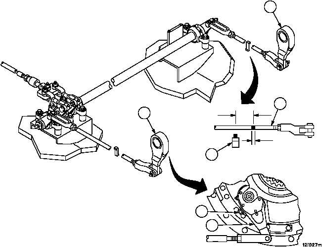
Adjustment
1. Make sure brake linkage is in the relaxed position (not applied) (TM 9--2350--292--10).
2. Place a 0.05 inch (12.7 mm) wide mark on each rear brake rod assembly (1). The centerline of the mark must be
3.0--in. (76.2 mm) from the centerline of the brake adjustment indicator (2).
3. Apply brake fully and note position of mark with respect to brake adjustment indicator (2). If mark and brake ad-
justment indicator (2) do not align, release brake, adjust brake apply levers (3) using adjusting screw (4) until
mark and brake adjustment indicator (2) align when brake is applied.
Figure 169
2
1
3
3
3
4
(76.2 MM)
0.50 IN
(12.7 MM)
3.0 IN