TM 9--2350--292--20--2
0357 00--3
BRAKE LINKAGE ALIGNMENT, ADJUSTMENT AND BLEEDING
(NEW CONFIGURATION WITH BRAKE MODULATION) -- CONTINUED
0357 00
Alignment -- Continued
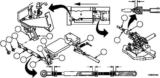
WARNING
A minimum thread engagement of 0.50 inch (12.7 mm)
between brake cable assembly and clevis must be main-
tained at all times. Failure to comply could result in as-
sembly separation, causing loss of vehicle service
brakes, resulting in personnel injury or vehicle damage.
9. Attach brake cable assembly (2) to clevis (3). Verify that a thread engagement of 0.50 inch (12.7 mm) between
threaded rod portion of brake cable assembly (2) and clevis (3) exist. Torque nut (1) to 15--20 lb--ft ) (20--27 NSm).
10. Remove cotter pin (14), nut (15), flat washer (16) and rod assembly (17) from lever (18). Discard cotter pin.
11. Disconnect rod assembly (19) from lever assembly (20) (WP 0367 00).
12. With the shift lever in “PARK”, restrain brake lever in the “up” position.
WARNING
A minimum thread engagement of 0.62 inch (15.7 mm)
between rod assembly and clevis must be maintained at
all times. Failure to comply could result in assembly sep-
aration, causing loss of vehicle service brakes, resulting
in personnel injury or vehicle damage.
13. Loosen two nuts (21) and maximize the length of rod assembly (17) so that when rod assembly (17) is attached to
lever assembly (22), clevis (23) is within 0.12 inch (3.0 mm) of contacting brake shaft (24).
14. Verify thread engagement of 0.62 inch (15.7 mm) exists between ends of rod assembly (17) and clevis (23 and
25). Tighten two nuts (21).
15. Connect rod assembly (17) to lever (18) with flat washer (16), nut (15) and new cotter pin (14).
22
20
19
24
23
21
21
17
0.62 IN
(15.7 MM)
0.62 IN
(15.7 MM)
0.62 IN
(15.7 MM)
18
15
16
14
FORWARD
0.50 IN
(12.7 MM)
1
2
3
25